埋弧焊系统控制方案设计及算法研究
VIP免费

摘 要
本文介绍了焊接的定义、发展历史以及焊接质量的影响因素,论述了焊接自
动化和智能化在焊接技术领域的重要性和必要性。重点讲述了埋弧焊的特点以及
其相对于传统手工焊的优点,进一步分析了国内外的研究现状。在理论上,通过
对埋弧焊系统的工作原理、电弧静特性和弧焊电源外特性进行分析,建立了该系
统的数学模型。
埋弧焊系统的送丝方式有两种,即等速送丝方式和变速送丝方式。根据具体
的焊接工艺和适用范围,为了获得快速实时的控制效果,确保焊接质量,本文选
用变速送丝方式。结合得出的埋弧焊系统模型,提出了相应的变速送丝控制方案,
给出了焊接电弧和送丝速度之间的关系式。
目前,埋弧焊控制系统中对焊接参数的控制,大都采用的是 PI 控制,这样虽
然可以简化运算过程和便于参数调整,并且避免了加入微分项所造成的控制过程
占用过多的时间。但是,没有了微分控制,缺少了对提前获取到的误差的变化趋
势所进行的超前调节,会使得系统的动态特性不足。本论文采用的是 HCMAC 和
PID 的复合控制方案,一方面加入了微分控制,用来来提高系统的动态特性;另
一方面,通过使用前馈网络和反馈网络的复合控制,再结合神经网络的相关算法,
去减少加入微分项所增加的控制时间。
在送丝电机控制上,利用上述复合控制方案来调节直流电机电枢电压,来调
节送丝速度。经过理论分析后,利用 Matlab/Simulink 对埋弧焊控制系统进行了一
系列的仿真实验,取得了很好的控制效果。
以Microchip 公司的 PIC24H 系列单片机为控制核心,结合该系列单片机的功
能和特性,进一步设计和完善了埋弧焊控制系统的硬件平台。PIC24H 系列单片
机是 16 位高性能单片机,不仅迎合了市场对低成本、高性能的需求,同时,PIC24H
系列单片机也能够适用于像埋弧焊过程这样对工业环境要求苛刻的场所。
最后在搭建好的硬件平台上,通过模块化的软件设计方法,进一步设计了埋
弧焊控制系统的软件,实现了埋弧焊系统的数字化控制。
关键词:埋弧自动焊 变速送丝 HCMAC 模块化软件设计
ABSTRACT
This paper introduces welding definition, history and the affecting factors of
welding quality. It also discusses the importance and necessity of welding automation
and intelligence in the field of welding technology. The characteristic and the
advantages compared to manual welding are emphasized in the paper. What’s more,
it also has a further analysis of the research status both at home and abroad. Through
theoretically in-depth analysis and research of submerged arc welding system, combing
with the principle of submerged arc welding system, the implementation of the specific
process, arc static characteristic and the welding power source external characteristic,
the mathematical model of the system is established.
There are two kinds of submerged arc welding wire feeding ways, namely
constant speed wire feeding way and variable speed wire feeding way. Depending on
the welding process and the applicable scope, in order to obtain rapid real-time control
effect and ensure the welding quality, this article selects the variable speed wire
feeding way. The corresponding variable speed wire control scheme is put forward
combined by the model, which can solve stable relationship between wire feeding
speed and electric arc.
At present, the PI control is still the mostly used control way in the control of
submerged arc welding parameters, which can not only simplify operation process and
make the parameters convenient to be adjusted, but also save the control time which
caused by the differential control. However, the system dynamic characteristics will be
really bad for the lack of differential control, which can predict the trend of the error
change and give an advance adjust for it. This paper adopts HCMAC and PID
combined control scheme. On the one hand, the scheme joins the differential control to
strengthen the dynamic characteristics of the system. On the other hand, by using
compound control of feed-forward and feedback network, combined with neural
network algorithm, to cut the control time which is caused by joining the differential
item.
In view of the wire feeding motor, using the former control scheme to adjust the
DC motor armature and the wire feeding speed. After theoretical analysis and research,
Matlab/Simulink is used to simulate the control system, which finally reaches an
expected control demand.
With microchip company PIC24H series as the control core, combing with its
features, the hardware platform of the submerged arc welding control system is
designed. PIC24H series single chip microcomputer is a 16-bit high-performance
single chip microcomputer, which not only can cater to the market demand for low cost
and high-performance, but also can apply to the severely working environment such as
the place of submerged arc welding.
Finally, after designing the hardware platform, through the modular software
design method, the software of the control system of the submerged arc welding is also
designed. All of these make the welding system realize a digital control.
Key Word: Submerged Arc Welding, Variable Feeding Wire, Hyper-
ball Cerebellar Model Articulation Controller, Modular
Software Design
目 录
中文摘要
ABSTRACT
第一章 绪 论............................................................................................................1
1.1 课题来源及背景.............................................................................................1
1.2 埋弧焊简述.....................................................................................................1
1.3 埋弧焊机控制系统的发展现状.....................................................................3
1.3.1 国内埋弧焊机控制系统发展现状 ........................................................3
1.3.2 国外埋弧焊机控制系统发展现状 ........................................................3
1.4 本论文的主要研究内容.................................................................................4
1.5 本论文的组织结构.........................................................................................4
第二章 埋弧焊系统建模..........................................................................................6
2.1 埋弧焊工作原理分析 ...................................................................................6
2.2 焊接电弧静特性 ...........................................................................................7
2.3 弧焊电源 .......................................................................................................8
2.3.1 弧焊电源外特性 ....................................................................................8
2.3.2 弧焊电源选型 ........................................................................................9
2.4 埋弧焊系统模型建立 .................................................................................10
2.4.1 埋弧焊系统回路模型 ..........................................................................10
2.4.2 焊丝干伸长的电压降子模型 ..............................................................11
2.4.3 熔滴电压降子模型 ..............................................................................12
2.4.4 电弧电压降模型 ..................................................................................14
2.4.5 电弧动态模型分析................................................................................14
第三章 埋弧焊系统控制方案................................................................................16
3.1 埋弧焊系统送丝方式...................................................................................16
3.1.1 等速送丝方式 ......................................................................................16
3.1.2 变速送丝方式 ......................................................................................17
3.2 变速送丝系统控制方案...............................................................................19
3.3 送丝电机选型...............................................................................................20
3.4 送丝电机调速方法.......................................................................................21
第四章 埋弧焊控制系统硬件设计........................................................................22
4.1 控制板设计的注意要求 .............................................................................22
4.2 微控制器选型 .............................................................................................23
4.3 控制系统硬件结构图 .................................................................................24
4.4 A/D 模块电路设计 ......................................................................................25
4.5 电机驱动模块设计 .....................................................................................26
4.6 显示模块设计 .............................................................................................39
4.7 硬件抗干扰设计 .........................................................................................31
第五章 埋弧焊控制系统软件设计........................................................................32
5.1 MPLAB 开发环境简介.................................................................................32
5.2 控制系统软件流程 .....................................................................................32
5.2.1 引弧子程序 ..........................................................................................33
5.2.2 收弧子程序 ..........................................................................................34
5.3 HCMAC 结构及算法 ..................................................................................35
5.4 HCMAC 与PID 复合控制 ......................................................................... 37
5.5 软件防干扰设计 .........................................................................................37
第六章 埋弧焊控制系统仿真及调试....................................................................38
6.1 埋弧焊控制系统仿真 .................................................................................38
6.2 弧压反馈仿真 .............................................................................................41
6.3 埋弧焊控制系统调试...................................................................................42
6.4 系统完善的建议 .........................................................................................43
第七章 总结与展望................................................................................................45
7.1 总结 .............................................................................................................45
7.2 展望 .............................................................................................................45
参考文献..................................................................................................................47
在读期间公开发表的论文......................................................................................50
致谢..........................................................................................................................51

第一章 绪论
1
第一章 绪 论
1.1 课题来源及背景
焊接是经过加压、加热或者两者同时使用的方法,在焊接过程中,通过采用
或者不采用特定的填充材料,最终使得待焊工件实现原子结合的一种加工方法[1]。
作为一种金属连接工艺,焊接既可以连接同一种金属,也可以在实现不同属性的
合金和金属的连接[2]。
随着焊接工艺的发展和完善,焊接已经成为国民经济发展和现代化工业控制
中不可或缺的产业,并广泛应用于能源工业的石油、天然气管道,交通,汽车工
业,造船,航天建筑等领域。但是,在实际生产中,由焊接带来的噪声、有害气
体、高频电磁辐射以及焊接烟尘等对焊接操作人员伤害很大。因此,焊接自动化
以及比自动化更先进的智能化控制已经成为并且将一直是相关技术人员研究的重
要课题之一。
在实际的焊接过程中,为了获得良好的焊接质量,无论是电弧电压还是焊接
电流都需要保持稳定的供给。焊丝的燃烧会使得焊丝缩短,为了保持焊接继续进
行,必须进给焊丝,但是焊丝的进给速度过快或过慢,都会使得电弧电压和焊接
电流等参数发生波动。如果焊接电流过大,可能造成焊剂的堆积,甚至造成待焊
工件的损坏或烧穿;如果焊接电流过小,则会造成焊丝和焊件熔化不充分,产生
气泡等。焊接小车的行走速度同样是影响焊接质量的一个关键因素,如果小车行
走速度过快,会使得焊接不充分甚至造成电弧熄灭;如果小车行走速度过慢,又
会造成待焊工件的损坏甚至焊剂的堆积。
1.2 埋弧焊简述
埋弧焊(全称埋弧自动焊),它是利用焊件和焊丝燃烧的电弧所产生热量,
去熔化焊剂、焊丝以及母材金属,从而形成焊缝并最终连接被焊工件。
通常情况下,习惯将埋弧焊分为自动焊和半自动焊。两者的区别是:前者电
弧的相对移动和焊丝的送进都是自动的,而后者电弧移动是手动的,焊丝送进则
是自动的[3]。
在焊接过程中,焊接电源的两极分别接至焊件与导电嘴,焊剂由焊剂漏斗经
软管堆敷到焊件的待焊处,送丝电机把焊丝经过导电嘴送入焊接区。电弧燃烧所
得的电弧热使焊剂、焊丝以及母材局部熔化蒸发。熔化的焊剂在由焊接过程中各
种蒸气所形成的空腔中,变成一层熔渣膜。这层熔渣膜使得液体金属、电弧与外
界的空气隔离,并且可以有效的防止弧光外射。局部熔化的母材,会在空腔的底
部形成熔池。熔化的焊丝形成熔滴,在空腔的上部,除了少数熔滴自由过渡外,
大多数的熔滴是以渣壁过渡的形式慢慢的向熔池中过渡[4]。

摘要:
展开>>
收起<<
摘要本文介绍了焊接的定义、发展历史以及焊接质量的影响因素,论述了焊接自动化和智能化在焊接技术领域的重要性和必要性。重点讲述了埋弧焊的特点以及其相对于传统手工焊的优点,进一步分析了国内外的研究现状。在理论上,通过对埋弧焊系统的工作原理、电弧静特性和弧焊电源外特性进行分析,建立了该系统的数学模型。埋弧焊系统的送丝方式有两种,即等速送丝方式和变速送丝方式。根据具体的焊接工艺和适用范围,为了获得快速实时的控制效果,确保焊接质量,本文选用变速送丝方式。结合得出的埋弧焊系统模型,提出了相应的变速送丝控制方案,给出了焊接电弧和送丝速度之间的关系式。目前,埋弧焊控制系统中对焊接参数的控制,大都采用的是PI控制...
相关推荐
-
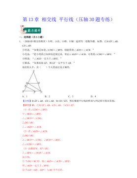
七年级数学下册(易错30题专练)(沪教版)-第13章 相交线 平行线(原卷版)VIP免费
 2024-10-14 25
 -
七年级数学下册(易错30题专练)(沪教版)-第13章 相交线 平行线(解析版)VIP免费
 2024-10-14 28
 -
七年级数学下册(易错30题专练)(沪教版)-第12章 实数(原卷版)VIP免费
 2024-10-14 27
 -
七年级数学下册(易错30题专练)(沪教版)-第12章 实数(解析版)VIP免费
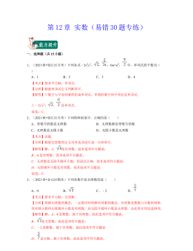 2024-10-14 19
 -
七年级数学下册(压轴30题专练)(沪教版)-第15章平面直角坐标系(原卷版)VIP免费
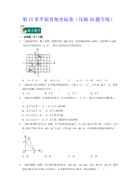 2024-10-14 19
 -
七年级数学下册(压轴30题专练)(沪教版)-第15章平面直角坐标系(解析版)VIP免费
 2024-10-14 27
 -
七年级数学下册(压轴30题专练)(沪教版)-第14章三角形(原卷版)VIP免费
 2024-10-14 19
 -
七年级数学下册(压轴30题专练)(沪教版)-第14章三角形(解析版)VIP免费
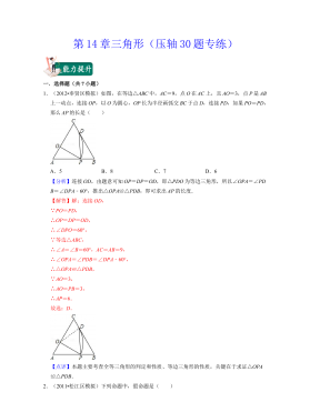 2024-10-14 30
 -
七年级数学下册(压轴30题专练)(沪教版)-第13章 相交线 平行线(原卷版)VIP免费
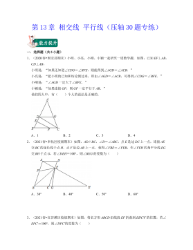 2024-10-14 26
 -
七年级数学下册(压轴30题专练)(沪教版)-第13章 相交线 平行线(解析版)VIP免费
 2024-10-14 22
作者:侯斌
分类:高等教育资料
价格:15积分
属性:54 页
大小:3.35MB
格式:PDF
时间:2024-11-19
相关内容
-
七年级数学下册(压轴30题专练)(沪教版)-第15章平面直角坐标系(解析版)
分类:中小学教育资料
时间:2024-10-14
标签:无
格式:DOCX
价格:15 积分
-
七年级数学下册(压轴30题专练)(沪教版)-第14章三角形(原卷版)
分类:中小学教育资料
时间:2024-10-14
标签:无
格式:DOCX
价格:15 积分
-
七年级数学下册(压轴30题专练)(沪教版)-第14章三角形(解析版)
分类:中小学教育资料
时间:2024-10-14
标签:无
格式:DOCX
价格:15 积分
-
七年级数学下册(压轴30题专练)(沪教版)-第13章 相交线 平行线(原卷版)
分类:中小学教育资料
时间:2024-10-14
标签:无
格式:DOCX
价格:15 积分
-
七年级数学下册(压轴30题专练)(沪教版)-第13章 相交线 平行线(解析版)
分类:中小学教育资料
时间:2024-10-14
标签:无
格式:DOCX
价格:15 积分