下置凸轮配气机构仿真设计研究

VIP免费
3.0 陈辉 2024-11-19 4 4 1.41MB 82 页 15积分
侵权投诉
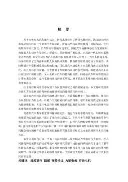
摘 要
发动机凸轮型线的设计关系到汽车的动力性、经济性和可靠性。随着汽车产
品更新换代速度的加快和使用要求的不断提高,优化设计和快速开发已成为发动
机产品开发设计中亟待解决的课题。当发动机的总体布置结构、目标参数和综合
限定条件确定后,配气机构零件的结构设计在很大程度上受到了边界条件的制约,
配气机构设计的重点已转移到凸轮型线的设计上来。由于发动机凸轮型线受配气
系统结构和型线设计参数的影响,以往各参数间的匹配、优选和调整,往往需要
进行大量的反复试算、试验,并依靠丰富的设计经验才能完成。对于这样一个需
要反复精确计算,不断通过试验来改进的繁琐过程,仅仅依靠设计师的手工计算
和有限的经验是很难取得理想的效果的,而且开发周期长、成本高,设计精度难
以控制。先进而实用的设计方法仅掌握在少数国外汽车及发动机公司,但出于商
业利益考虑,他们不可能公开其技术。现有的商业化软件 ADAMSAVL 等则主
要用于配气机构的模拟分析计算和性能评价,而不是设计。因此,有必要利用计
算机技术对配气机构进行仿真设计,以满足我国汽车发动机自主开发的需要。
本文以下置凸轮配气机构为研究对象,在剖析目前配气机构设计理论和设计
方法的基础上,结合现代数理方法和电子计算机技术,实现了凸轮型线的数字化
设计,简化了设计过程;应用机械振动理论建立了下置凸轮配气机构的多质量动
力学模型,对机构的运动、受力、润滑等状态进行了仿真分析,分析结果更接近
实际,便于对配气机构动力学性能作出合理的评价,为配气机构的设计开发和性
能改善提供了依据。
基于 C++ Builder 6.0 MATLAB 7.1 软件平台,开发了一款界面友好,操作
简单的下置凸轮配气机构仿真设计软件。该软件具备较强图形和数据处理能力,
为发动机配气机构的设计开发和性能优化提供了便捷的工具,提高了设计效率,
缩短了开发周期,降低了开发成本。
关键词:配气机构 动力学 仿真 设计
ABSTRACT
The engine cam design is related to the automobile’s power performance, economy
performance, reliability performance and emission performance. With the accelerated
pace of automotive products replacement and the continuous improvement of
requirements, optimal design and rapid development have become the issues which
need to be resolved during the engine products development. When the overall layout
structure, goal parameters and comprehensive limiters of the engine are determined, the
structural design of the valve train parts is mainly restricted by the boundary conditions.
The focus of valve train design has shifted to the cam profile design. As the engine cam
profile is affected by valve train’s structure and cam profile’s design parameters, the
matching, optimization and adjustment of the parameters usually requires a lot of
repeated calculation, testing, and relies on extensive experience to be completed. For
such a trivial process, it is difficult to achieve the desired results just by the designers’
hand calculations and limited experience, which is characterized with long development
cycle, heavy cost and difficult control on the design precision. The advanced and
practical method is held only by few foreign advanced motor companies. But for
commercial interests, they can not open their skills. The existing commercial software
ADAMS, AVL, etc. are mainly used in the simulation analysis and performance
evaluation of valve train, rather than design. Therefore, it is necessary to use computer
technology to design valve train to meet China's self-developed automobile engine
needs.
In this paper, the author takes the push-rod valve train as the research object,
analyzes the current valve train design theory and design method, and uses modern
mathematical methods and computer technology to achieve the digital design of cam
profile, and simplify the design process; a multi-mass dynamic model with the push-rod
valve train has been created based on mechanical vibration theory; the movement,
mechanical and lubrication status of the valve train has been simulated and analyzed,
and the results of simulation analysis are closer to reality, which is convenient for
making a reasonable assessment for the valve train’s dynamic performance, and
provides basis for the valve trains development and performance improvement.
Based on C + + Builder 6.0 and MATLAB 7.1 software platform, a simulation
design software applying to push-rod valve train has been developed, which not only
has a friendly interface and easy-to-operate, but also has a strong graphics and data
processing capability. The software can provide a convenient tool for the engine valve
train’s development and performance improvement, enhance the design efficiency,
shorten the development cycle and lower the development cost.
Key WordsValve Train, Dynamics, Simulation, Design
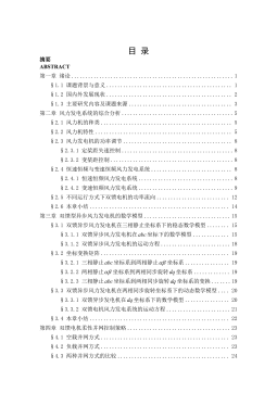
目 录
中文摘要
ABSTRACT
第一章 .................................................................................................................1
§1.1 课题来源 ..............................................................................................................1
§1.2 课题意义 ..............................................................................................................1
§1.3 国内外研究概况 ..................................................................................................1
§1.4 课题主要研究内容 ..............................................................................................3
第二章 凸轮型线设计 .................................................................................................... 4
§2.1 对称式复合函数凸轮型线设计 ..........................................................................4
§2.1.1 缓冲段设计 ...................................................................................................5
§2.1.2 工作段设计 ...................................................................................................6
§2.2 复合函数凸轮型线的非对称设计 ......................................................................7
§2.3 凸轮型线设计结果与分析 ..................................................................................8
§2.3.1 对称凸轮型线与非对称凸轮型线的对比分析 ...........................................8
§2.3.2 设计参数对凸轮型线性能的影响 ...............................................................9
§2.4 本章小结 ............................................................................................................14
第三章 下置凸轮配气机构运动学分析 ...................................................................... 15
§3.1 平底挺柱的运动规律 ........................................................................................15
§3.2 凸轮外形与平底挺柱运动规律间的关系 ........................................................16
§3.3 球面挺柱的运动规律 ........................................................................................17
§3.4 气门的运动规律 ................................................................................................19
§3.5 本章小结 ............................................................................................................20
第四章 下置凸轮配气机构动力学模型的建立与求解 .............................................. 21
§4.1 配气机构动力学分析方法 ................................................................................21
§4.1.1 配气机构动力学物理建模方法分析 .........................................................21
§4.1.2 配气机构动力学数学建模方法分析 .........................................................23
§4.1.3 配气机构动力学方程数值解法分析 .........................................................25
§4.2 下置凸轮配气机构建模思路与过程 ................................................................28
§4.2.1 建模方法与数值解法的确定 .....................................................................28
§4.2.2 多质量动力学模型的建立 .........................................................................29
§4.2.3 多自由度系统动力学方程参数的确定 .....................................................32
§4.2.4 多质量动力学模型的求解 .........................................................................34
§4.3 本章小结 ............................................................................................................40
第五章 仿真计算结果分析 .......................................................................................... 41
§5.1 气门运动规律分析 ............................................................................................41
§5.2 气门弹簧变形分析 ............................................................................................44
§5.3 气门与活塞运动干涉分析 ................................................................................46
§5.4 气门落座力分析 ................................................................................................49
§5.5 凸轮-挺柱接触应力分析 .................................................................................. 52
§5.5.1 发动机转速对凸轮-挺柱接触应力的影响 ............................................... 53
§5.5.2 曲率半径对凸轮-挺柱接触应力的影响 ................................................... 55
§5.5.3 气门弹簧刚度和预紧力对凸轮-挺柱接触应力的影响 ........................... 56
§5.6 凸轮-挺柱弹流动力润滑分析 .......................................................................... 57
§5.6.1 稳态油膜厚度计算 .....................................................................................58
§5.6.2 动态油膜厚度计算 .....................................................................................61
§5.6.3 凸轮润滑特性的评定 .................................................................................63
§5.7 本章小结 ............................................................................................................64
第六章 下置凸轮配气机构仿真设计软件的开发 ...................................................... 66
§6.1 数值计算工具的选择 ........................................................................................66
§6.2 可视化开发工具的选择 ....................................................................................67
§6.3 应用程序接口设计 ............................................................................................67
§6.4 交互仿真界面设计 ............................................................................................68
§6.5 本章小结 ............................................................................................................72
第七章 总结与展...................................................................................................... 73
§7.1 全文总结 ............................................................................................................73
§7.2 论文的创新点 ....................................................................................................73
§7.3 后续工作展望 ....................................................................................................74
参考文献 .........................................................................................................................75
在读期间公开发表的论文和承担科研项目及取得成............................................ 78
.............................................................................................................................79
第一章 绪
1
第一章 绪
§1.1 课题来源
本学位论文课题来源于上海柴油机股份有限公司项目——SC9DK 发动机凸
轮型线改进设计。
§1.2 课题意义
随着汽车产品更新换代速度的加快和使用要求的不断提高,优化设计和快速
开发已成为发动机产品开发设计中亟待解决的课题。如何在最短的时间内提供环
保、经济、可靠的汽车产品,成为汽车制造商们面临的挑战。配气机构是发动机
中结构复杂、工作频繁的部件之一,它承受强烈的热负荷和机械负荷,其设计是
否合理,对发动机的动力性、可靠性、噪声和排放等有着关键影响。
发动机配气凸轮机构的设计主要是凸轮型线的设计,它对整个配气机构的性
能具有决定性的影响。在凸轮型线的设计过程中,由于各设计参数关联密切,相
互制约,同时又对发动机充气性能、机构运动状态、各运动件的可靠性有交错和
连带的影响。因此,要将这种错综复杂的关系理清楚,需要经过大量的精确运算、
反复调整及合理的取舍,来验证这个复杂过程。同时,还要考虑型线设计与整机
的匹配问题以及对整机性能的影响,这就需要建立配气机构的简化模型,对配气
机构的相关特性参数进行计算和分析。传统的配气机构设计是把机构简化为纯刚
体分析,这样在设计过程中,只能将许多关键的因素排除在外,无法考虑弹性变
形带来的影响,致使发动机的动力性、经济性和机构的可靠性不能得到保障。为
了更精确地分析配气机构的特性参数,需要建立配气机构的多质量动力学模型,
运用动力学分析方法进行分析计算。面对上述大量参数的反复计算、匹配和调整,
仅靠手工计算进行设计参数的优选,不仅很难取得理想的设计效果而且计算周期
长、效率低、成本高,同时修正设计过程繁琐,不能适应快速修改和换型改进的
需要。
CAD/CAE 软件为发动机的设计环节带来了革命性的变化,在制造出物理样
机之前即可对设计对象的性能作出准确的预测。这不仅减少和部分代替了工程测
试与分析的环节,缩短了产品开发周期,更大大提高了设计质量。当前,
ADAMS
Ricardo AVL 都有专门针对发动机配气机构设计与分析的模块。然而,无论那
家公司的 CAD/CAE 产品,其主要功能都是对已有的设计结果进行模拟计算分析,
而其设计功能相对较弱,对使用者而言完全是黑箱操作。为了满足发动机配气机
构自主开发的需要,剖析目前配气机构的设计理论和设计方法,探讨一种新颖的
摘要:

摘要发动机凸轮型线的设计关系到汽车的动力性、经济性和可靠性。随着汽车产品更新换代速度的加快和使用要求的不断提高,优化设计和快速开发已成为发动机产品开发设计中亟待解决的课题。当发动机的总体布置结构、目标参数和综合限定条件确定后,配气机构零件的结构设计在很大程度上受到了边界条件的制约,配气机构设计的重点已转移到凸轮型线的设计上来。由于发动机凸轮型线受配气系统结构和型线设计参数的影响,以往各参数间的匹配、优选和调整,往往需要进行大量的反复试算、试验,并依靠丰富的设计经验才能完成。对于这样一个需要反复精确计算,不断通过试验来改进的繁琐过程,仅仅依靠设计师的手工计算和有限的经验是很难取得理想的效果的,而...

展开>> 收起<<
下置凸轮配气机构仿真设计研究.pdf

共82页,预览9页

还剩页未读, 继续阅读

作者:陈辉 分类:高等教育资料 价格:15积分 属性:82 页 大小:1.41MB 格式:PDF 时间:2024-11-19

开通VIP享超值会员特权

  • 多端同步记录
  • 高速下载文档
  • 免费文档工具
  • 分享文档赚钱
  • 每日登录抽奖
  • 优质衍生服务
/ 82
客服
关注