压水堆核电站多级限流孔板设计方法及其试验研究

VIP免费
3.0 陈辉 2024-11-19 4 4 1.4MB 81 页 15积分
侵权投诉
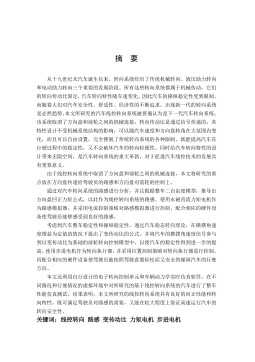
摘 要
限流孔板是用于系统中的流体(各种液体和气体)在管道中流动时进行能量
交换和转移的过程中按一定运行工况要求降低静压的装置,是服务于蒸汽供应系
统(NSSS)和核岛配套设施(BNI)的辅助装置,是压水堆核电站中不可缺少的
辅助设备。国内核电站中所用的多级限流孔板由于设计计算比较困难,基本上由
国外进口,但是根据我国核电的发展趋势,多级孔板的国产化是必要的,也是必
然的。本课题来源于秦山二期核电站扩建工程,首先,基于限流孔板节流原理,
推导出三条重要推论,并在此基础上,分别对标准限流孔板,特殊限流孔板和多
级限流孔板进行了设计计算。然后分别研究和讨论了限流孔板、联接螺栓和法兰
的强度,并对限流孔板进行了抗震分析。最后,设计出限流孔板流动性试验平台,
验证了限流孔板的设计和计算方法的正确性。论文所做的工作主要体现在以下几
个方面:
1理论研究:具体地介绍了限流孔板的功能、分类和节流原理,然后通过对
GB/T2624.2-2006/ISO5167-2:2003 的分析,总结出三点重要推论,为非标准限流孔
板的设计计算提供了理论依据。
2、设计计算:标准限流孔板是基于 GB/T 2624.2-2006《用安装在圆形截面管
道中的差压装置测量满管流体流量 2部分:孔板》中所提的迭代法设计计算的。
小孔径限流孔板的设计主要采用最小二乘法,拟合出一条关于
ReD
的三维
曲线,并得出
ReD
的关系式。多级限流孔板的设计计算,没有可供依据的
标准可循,主要根据经验公式,参考系统运行要求及安装空间,确定有关的结构
参数。
3、安全分析:计算了单板孔板、特殊孔板和多级孔板的应力并对其进行了
强度校核;然后分别对单板孔板、特殊孔板和多级孔板进行了抗震分析与计算;
介绍了联接螺栓和法兰的应力计算方法,并对它们的强度进行了校核。
4限流孔板流动性能试验台的设计:介绍了限流孔板流动性能试验台的设计。
对各个种类的泵和流量计进行了详细的比较和说明,然后具体的介绍了流动性能
试验的试验条件、试验步骤、数据处理和误差分析等。
5、数据采集及相应界面设计:对数据采集卡 USB-9211 进行了介绍,然后
体地得介绍了整个数据采集处理系统,并且详细地描述了各个工作模块。设计的
限流孔板流动性能试验台将实现流量压力与实际工况一致,并且使用数据采集卡
直接从传感器中采集数据,用高级语言编写软件,对采集的数据进行处理,计算
出雷诺数
ReD
和阻力系数
绘制出雷诺数
ReD
和阻力系数
的曲线图。当雷诺数
足够大时,将限流孔板的阻力系数
值与限流孔板实际运行工况下要求的阻力系数
值进行比较,即能验证限流孔板的结构设计性能。
本文的理论研究和实验结果均表明,限流孔板的设计方法是正确可行的,有
重要的理论意义和实用价值。
关键词:核电站 限流孔板 最小二乘法 阻力系数 强度校核
ABSTRACT
The restriction orifice is a device used in the system's fluid (each kind of liquid and
gas) flows in the pipeline. It can reduce static pressure according to certain operating
condition in the exchange and transfer of energy process. It is indispensable auxiliary
equipment served in NSSS and BNI in a pressurized water reactor nuclear power plant.
The domestic multi-level restriction orifice used in nuclear power plant is basically
imported from abroad because the design and calculation is difficult. However, the
localization of multi-level restriction orifice is necessary and inevitable according to
China's nuclear power development trend. This research comes from Qinshan nuclear
power plant second phase expand project. First of all, we derived three important
inferences based on the throttling principle of restriction orifice. And on this basis, the
standard restriction orifice, special restriction orifice and multi-level restriction orifice
design calculations have been carried out respectively. And then we studied and
discussed the strength of restriction orifice, attachment bolt and flange. The
earthquake-resistant analysis of restriction orifice has been carried out. Finally, we
designed a flow property test-bed of restriction orifice to verify the validity of
restriction orifice’s design and calculation method. The major works of this paper were
as follows:
1. Principle research: This paper specifically describes the restriction orifice
functions, classifications and the principles of throttling, and analyses
GB/T2624.2-2006/ISO5167-2:2003, and then sums up three important deductions. It
provides a theoretical basis for the design calculation of the non-standard restriction
orifice.
2. Design calculation: The design calculation of standard restriction orifice is based
on GB/T2624.2-2006
The differential pressure devices installed in circular section pipe
measure full bobbin fluid flow. Part 2: Orifice . The design of small-aperture
restriction orifice mainly uses least square method to fit out a three-dimensional curve
of
and
ReD
, and derive the relationship of
and
ReD
. To multi-level
restriction orifice design calculations, there is no basis for the standard to follow. It
mainly based on empirical formulas, and referenced system operating requirements and
the installation space to determine the structural parameters.
3. Safety analysis: The paper calculated the stress of single-stage restriction orifice,
special restriction orifice and multi-level restriction orifice, and check of their strength.
Then the earthquake-resistant analyses and calculations of single-stage restriction
orifice, special restriction orifice and multi-level restriction orifice have been carried out.
Simultaneously the paper described the attachment bolt and flange stress calculation
methods, and conducted a check of their strength.
4. Restriction orifice flow property test-bed design: The paper introduced the
design of restriction orifice flow property test-bed. It made detailed comparisons and
descriptions of the various types of pumps and flow meters, and then introduced the
flow property test’s test conditions, test steps, data processing and error analysis and so
on.
5. Data acquisition and the GUI design: The USB-9211 data acquisition card was
introduced. And then the entire data acquisition and processing system was introduced
specifically, and the various process modules were described in detail. The designed
restriction orifice flow property test-bed achieved the same flow and pressure as the
actual working conditions. The data acquisition card acquires data directly from the
sensors, and use high-level language to write software for processing data acquired.
Then calculate the Reynolds number and drag coefficient, drawing out the curve of the
Reynolds number and. When the Reynolds number is large enough, we compare the
drag coefficient of restriction orifice to the actual operating conditions required drag
coefficient. That is able to verify the structural design performance of restriction orifice.
This theoretical research and experimental results show that the restriction orifice
design method is correct and feasible, and there are important theoretical significance
and practical value.
Key Word Nuclear power plant, Restriction orifice, least square
method, Drag coefficient, Strength checking
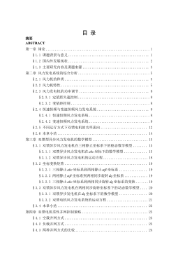
目 录
中文摘要
ABSTRACT
第一章 绪 论...................................................................................................................1
§1.1 课题的来源及意义.........................................................................................1
§1.2 国内外研究水平.............................................................................................2
§1.3 孔板的介绍.....................................................................................................4
§1.4 核电厂安全功能及分级[5] ..............................................................................5
§1.4.1 安全功能及分析方法.............................................................................6
§1.4.2 安全分级.................................................................................................6
§1.4.3 抗震分类.................................................................................................8
§1.5 本文的主要工作.............................................................................................8
第二章 限流孔板及其节流原理...................................................................................10
§2.1 限流孔板.......................................................................................................10
§2.1.1 限流孔板的功能和分类.......................................................................10
§2.1.2 限流孔板的节流原理...........................................................................11
§2.2 计算局部损失的普遍公式...........................................................................12
§2.2.1 管内流动突然扩大的局部损失...........................................................12
§2.2.2 计算局部损失的普遍公式...................................................................13
§2.2.3 局部阻力系数
的计算式 ................................................................... 13
§2.3 压力损失系数 K的确定..............................................................................14
§2.3.1 标准孔板压力损失系数 K的确定......................................................14
§2.3.2 非标准孔板及各种局部阻力件的压力损失系数的确定...................18
§2.4 本章小结.......................................................................................................18
第三章 限流孔板的设计计算.......................................................................................19
§3.1 管道内径大于 50mm 标准限流孔板的设计 .............................................. 19
§3.1.1 标准孔板的设计...................................................................................19
§3.1.2 基于 VB.NET 的设计界面及设计结果.............................................. 21
§3.2 管道内径小于 50mm 的小孔径限流孔板的设计 ...................................... 22
§3.2.1 利用量纲法对小孔径限流孔板设计...................................................22
§3.2.2 利用历史数据与试验方法对小孔径限流孔板设计...........................25
§3.3 特殊限流孔板设计计算...............................................................................28
§3.4 多级限流孔板设计计算...............................................................................29
§3.4.1 多级限流孔板的设计制造步骤...........................................................29
§3.4.2 多级限流孔板的设计计算...................................................................30
§3.5 采用的符号(包括单位)...........................................................................31
§3.6 本章小结.......................................................................................................32
第四章 限流孔板强度校核计算及抗震分析...............................................................34
§4.1 限流孔板的应力计算与强度校核...............................................................34
§4.1.1 应力计算公式.......................................................................................35
§4.1.2 强度条件...............................................................................................35
§4.1.3 应力计算与强度校核结果...................................................................35
§4.2 限流孔板的抗震分析与计算.......................................................................36
§4.2.1 限流孔板弯曲振动的固有频率计算...................................................37
§4.2.2 等效静力载荷计算...............................................................................37
§4.2.3 特殊限流孔板的抗震分析...................................................................38
§4.2.4 多级限流孔板的抗震分析...................................................................39
§4.2.5 计算结果...............................................................................................39
§4.3 联接螺栓预紧力计算及其强度校核...........................................................40
§4.3.1 记号及其定义.......................................................................................40
§4.3.2 预紧力的计算.......................................................................................41
§4.4 法兰应力计算与强度校核...........................................................................42
§4.4.1 记号及其定义.......................................................................................42
§4.4.2 弯矩的计算...........................................................................................44
§4.4.3 法兰应力计算.......................................................................................44
§4.4.4 法兰强度校核.......................................................................................45
§4.5 本章小结.......................................................................................................45
第五章 限流孔板流动性能试验平台设计与水压试验...............................................46
§5.1 限流孔板流动性能试验台的设计...............................................................46
§5.1.1 试验流程图与装置...............................................................................46
§5.1.2 泵的选择...............................................................................................48
§5.1.3 流量计的选择.......................................................................................49
§5.2 试验条件.......................................................................................................51
§5.2.1 流体条件...............................................................................................51
§5.2.2 试验环境温度.......................................................................................51
§5.2.3 试验压力...............................................................................................51
§5.2.4 试验管段...............................................................................................51
§5.2.5 取压口位置...........................................................................................51
§5.2.6 流量计的安装.......................................................................................52
§5.3 试验步骤.......................................................................................................52
§5.4 数据处理.......................................................................................................52
§5.5 误差分析.......................................................................................................53
§5.5.1 阻力系数
的相对标准偏差 ............................................................... 54
§5.5.2 运行流量条件
V
q设计
下的压降误差 ..................................................... 54
§5.5.3 运行压降条件
P设计
下的流量误差.....................................................54
§5.6 限流孔板水压试验.......................................................................................55
§5.6.1 试验装置...............................................................................................55
§5.6.2 试验要求...............................................................................................55
§5.6.3 水压试验的实施...................................................................................56
§5.6.4 水压试验的验收准则...........................................................................56
§5.6.5 水压试验结果.......................................................................................56
§5.7 本章小结.......................................................................................................57
摘要:

摘要限流孔板是用于系统中的流体(各种液体和气体)在管道中流动时进行能量交换和转移的过程中按一定运行工况要求降低静压的装置,是服务于蒸汽供应系统(NSSS)和核岛配套设施(BNI)的辅助装置,是压水堆核电站中不可缺少的辅助设备。国内核电站中所用的多级限流孔板由于设计计算比较困难,基本上由国外进口,但是根据我国核电的发展趋势,多级孔板的国产化是必要的,也是必然的。本课题来源于秦山二期核电站扩建工程,首先,基于限流孔板节流原理,推导出三条重要推论,并在此基础上,分别对标准限流孔板,特殊限流孔板和多级限流孔板进行了设计计算。然后分别研究和讨论了限流孔板、联接螺栓和法兰的强度,并对限流孔板进行了抗震分析...

展开>> 收起<<
压水堆核电站多级限流孔板设计方法及其试验研究.pdf

共81页,预览9页

还剩页未读, 继续阅读

作者:陈辉 分类:高等教育资料 价格:15积分 属性:81 页 大小:1.4MB 格式:PDF 时间:2024-11-19

开通VIP享超值会员特权

  • 多端同步记录
  • 高速下载文档
  • 免费文档工具
  • 分享文档赚钱
  • 每日登录抽奖
  • 优质衍生服务
/ 81
客服
关注