10kV混合型固态开关控制系统的研究
VIP免费
摘 要
随着供配电系统多元化、复杂化的发展,传统的机械式断路器、静止固态开
关已不能满足供配电系统对开关速动性及能耗性等方面的要求。因此,开展对适
用于供配电系统的高压大容量混合型固态开关的研究意义十分重大。
本文以 10kV 混合型固态开关为研究对象,详细分析了其工作原理。结合系
统性能指标要求,分析晶闸管的选取及晶闸管串联数量的确定方法。对单晶闸管
的RC 缓冲电路进行了研究,给出了适合工程应用的参数确定方法,并给出了算
例,进了 PSpice 仿真验证。对晶闸管串联均压,静态均压和动态均压进行了研
究,给出了静态均压电阻、动态均压电阻和电容的选参方法,并给出了算例,且
对动态均压过程进行了 PSpice 仿真。
本文详细介绍了 10kV 混合型固态开关控制系统的硬件和 DSP 软件设计。硬
件部分采用了 DSP 与FPGA 相结合的架构,分别以 DSP 芯片和 FPGA 芯片为中
心介绍了供电电路、时钟电路、仿真接口电路等基础外围电路及芯片对外接口电
路等的设计。软件部分按模块化设计的思想,分别对系统 DSP 程序的主程序、
启停状态机程序、模拟量采集程序、故障处理程序以及与上位机通信程序等程序
的设计进行了说明。
最后,本文使用了 Matlab/Simulink 与CCS 的联合仿真方法验证了本文所设
计的系统控制程序的合理性,并对在 Matlab/Simulink 和CCS 之间构建、实现联
合仿真的方法进行了详细说明。展示了 Level-2 Matlab S-Function 及M文件脚本
函数编写的关键步骤。本文所使用的联合仿真方法克服了在用 DSP 芯片进行系
统控制程序的设计、算法的验证时依赖于系统硬件的缺点,为系统控制程序的设
计带来了极大的便利。
本文的研究结果表明,本文把握住了 10kV 混合型固态开关控制系统的要求,
所设计的 DSP 程序逻辑合理,实现了混合型固态开关无涌流开通、零电流关断
等基本功能。
关键字
关键字关键字
关键字:
::
:10kV 混合型固态开关
混合型固态开关混合型固态开关
混合型固态开关 晶闸管串联均压
晶闸管串联均压晶闸管串联均压
晶闸管串联均压 联合仿真
联合仿真联合仿真
联合仿真 DSP
Level-2 Matlab S-Function
ABSTRACT
With the development of diversified and complicated power supply and
distribution system, traditional mechanical circuit breaker, static solid-state switch
cannot meet the requirements of the quick action and energy consumption. Therefore,
to carry out the applicable to power supply system of high voltage large capacity
hybrid solid-state switch is of significant importance to study.
The operational principle of the 10 kV hybrid solid-state switch is analyzed in
detail in this paper. Analysis of the thyristor selection and calculation method of
thyristor series number is given based on the system performance requirements. RC
snubber circuit of the single thyristor is studied and simulated in the PSpice, and a
suitable method for determing the parameter in engineering using is given. For series
thyristor, static volatage balancing circuit and dynamic volatage balancing circuit is
studied, and parameter determing method of the the static volatage balancing
resistance and dynamic volatage balancing resistance and capacitance is given. A
numerical example is showed out, and the simulation of the dynamic volatage
balancing circuit is excuted on the PSpice software.
The hardware and DSP software design of the 10 kV hybrid solid-state switch
control system is introduced in this paper. The DSP and FPGA architecture is used in
the hardware par.The DSP chip and FPGA chip are introduced for the center of
peripheral circuits, such as power supply circuit, clocking circuit and simulation
interface circuit, and external interface circuit. The idea of modular design is used in
the software par.The modular DSP program of the system are the main program,
start-stop state machine program, analog acquisition, fault handler and PC
communication program.
Finally, the Matlab/Simulink and CCS of the joint simulation method is used in
this paper to verify the rationality of the designed system control program. The
methods to build and realize the joint simulation between the Matlab/Simulink and
CCS is showed in detail. The key steps of how to write Level-2 Matlab S-Function
and script function of M file is given. The joint simulation method in this paper is to
overcome the system using DSP chip control program design and algorithm validation
depends on the shortcoming of the system hardware, for the design of the system
control program has brought great convenience.
The research results in this paper shows that the grasp of 10 kv hybrid solid-state

switch control system requirements, the design of DSP program logic is reasonable,
has realized the hybrid solid-state switch without open flow, the basic function such
as zero current turn off.
Key Word:
::
:10kV hybrid solid state switch,Thyristor series voltage
balancing, Collaborative simulation,DSP,Level-2MatlabS-Function
目 录
摘要
摘要摘要
摘要
ABSTRACT
第1章 绪 论 .......................................................................................................... 1
1.1 课题研究的背景及意义 ........................................................................... 1
1.2 混合型固态开关的研究现状 ................................................................... 4
1.3 本文的主要研究内容 ............................................................................... 7
第2章 10kV 混合型固态开关主电路拓扑及工作原理 ...................................... 8
2.1 混合型固态开关主电路拓扑结构 ........................................................... 8
2.2 混合型固态开关的工作原理 ................................................................... 8
2.3 混合型固态开关系统框图 ..................................................................... 10
2.4 系统的性能指标 ..................................................................................... 12
2.4.1 晶闸管的选取 .............................................................................. 12
2.4.2 单相阀组晶闸管数量计算 .......................................................... 13
2.5 单晶闸管 RC 缓冲电路研究 .................................................................. 15
2.5.1 晶闸管的关断过程分析 .............................................................. 15
2.5.2 RC 缓冲电路电容和电阻值的确定 ............................................. 16
2.5.3 计算举例及仿真研究 .................................................................. 18
2.6 串联晶闸管的静态均压与动态均压电路设计 ..................................... 21
2.6.1 串联晶闸管静态均压电阻 Rp的确定 ........................................ 21
2.6.2 串联晶闸管动态均压电阻和电容的确定 .................................. 22
2.6.3 计算举例及仿真研究 .................................................................. 22
2.7 本章小结 ................................................................................................. 24
第3章 控制系统硬件设计 .................................................................................. 25
3.1 控制主板硬件框图 ................................................................................. 25
3.2 DSP 芯片外围硬件电路的设计 .............................................................. 26
3.2.1 DSP 供电电路 ............................................................................... 26
3.2.2 DSP 时钟电路 ............................................................................... 26
3.2.3 JTAG 仿真接口电路 .................................................................... 27
3.2.4 串行通信接口电路 ...................................................................... 27
3.2.5 硬件复位电路 .............................................................................. 28
3.3 FPGA 芯片外围硬件电路的设计 ........................................................... 29
3.3.1 FPGA 供电电路 ............................................................................ 29
3.3.2 FPGA 时钟电路 ............................................................................ 30
3.3.3 FPGA 的AS 与JTAG 接口电路 ................................................. 30
3.3.4 FPGA 与信号接口连接电路 ........................................................ 31
3.3.5 FPGA 与A/D 芯片的电气连接 ................................................... 31
3.4 DSP 与FPGA 电气连接 .......................................................................... 32
3.5 本章小结 ................................................................................................. 32
第4章 控制系统软件设计 .................................................................................. 33
4.1 系统的主程序 ......................................................................................... 33
4.2 启停状态机程序 ..................................................................................... 34
4.3 模拟量的采集 ......................................................................................... 38
4.4 故障处理 ................................................................................................. 40
4.5 与上位机通信功能 ................................................................................. 41
4.5.1 Modbus 通信协议 ......................................................................... 41
4.5.2 循环校验码(CRC 码) ............................................................. 43
4.5.3 DSP 与上位机的通信流程 ........................................................... 45
4.5.4 DSP 与PC 通信演示 .................................................................... 46
4.6 本章小结 ................................................................................................. 48
第5章 系统在 Matlab/Simulink 与CCS3.3 联合仿真下的研究 ...................... 49
5.1 Matlab/Simulink 与CCS 简介 ................................................................ 49
5.2 Matlab 和CCS 联合仿真的基本原理 .................................................... 50
5.3 Matlab 与CCS 的连接方法 .................................................................... 52
5.4 S-Function 及脚本文件编写的操作方法 ............................................... 53
5.4.1 脚本文件编写中的关键步骤 ...................................................... 53
5.4.2 Level_2 Matlab S-Function 编写中的关键步骤 .......................... 55
5.5 Matlab 中混合型固态开关系统仿真模型的搭建 .................................. 56
5.6 仿真结果 ................................................................................................. 60
5.7 本章小结 ................................................................................................. 62
第6章 总结与展望 .............................................................................................. 63
6.1 总结 ......................................................................................................... 63
6.2 展望 ......................................................................................................... 64
附录 I ...................................................................................................................... 65

1
第1章 绪 论
1.1 课题研究的背景及意义
课题研究的背景及意义课题研究的背景及意义
课题研究的背景及意义
本课题来源于许继集团有限公司国家电网科技部项目。
自德国电气工程师奥古斯塔·劳西(ROS.August)提出了电气开关的概念后,
开关就成了电气领域所有电气应用中不可或缺的器件。经过一百多年的发展,开
关的种类丰富多样。按照用途分,有:电源开关、限位开关、转换开关、隔离开
关、行程开关等;按照结构分,有:微动开关、拨动开关、按钮开关、按键开关
等;按照接触类型分,有:A型触点(常开)开关、B型触点(常闭)开关和 C
型触点(常开和常闭)开关等;按照开关数分,有:单控开关、双控开关、多控
开关等;按照有无机械式运动部件分,有:机械开关、电子开关、机电混合式开
关等。
在输变电系统中,常用的开关是机械式断路器。它有机械开关共有的控制简
单、导通稳定、带负载能力强、投资低等优点,但其缺点也较为突出:无法定位
接通负载的时刻,在接通大功率负载时往往会伴随大的涌流,对电网产生一定的
冲击;在负载电流很大的场合断开负载时往往伴随着电弧产生
[1]
,易烧蚀触头,加
重了维护任务;由于是机械结构,其开通关断由机械零部件间的传动决定,有较
长的时间延迟,因而不能实时、灵活、快速地通断,易使事故扩大,破坏系统的
稳定性,难以满足一些电力用户对故障电流开断速动性的要求。同时,由于有直
接的应力作用于内部机械结构,导致相关的零部件容易磨损、老化,开断次数极
为有限,在运行过程中也常伴有噪声。
伴随着风能、光能等可再生能源的发展,产生了越来越多的分布式能源发电
微电网系统。这些微电网所拥有的电能已超出了本地的需求,需要将其接入大电
网,以实现能源的合理配置,避免浪费。分布式能源发电与传统的发电方式相比
持续性较差,因而微电网与大电网相比可靠性较差。为了避免微电网接入大电网
时对电网产生冲击
[2]
,影响电能质量,需要能对接入大电网的时刻有较好的定位。
此外,开关的速动性直接决定了能否及时将有故障微电网从大电网上切除。显然,
传统的机械式断路器较难满足这些需求。
得益于大功率可控硅技术的发展,以大功率可控硅为核心的固态开关
[3]
在可控
性及开关速动性上较之机械式断路器有了质的提升,能较好地满足微电网与大电
网连接时机及速动性的要求。固态开关工作时,通过对电压、电流的检测,在特
定的时刻通断可控硅器件,能有效避免合闸时涌流的产生。此外,固态开关在结

摘要:
展开>>
收起<<
摘要随着供配电系统多元化、复杂化的发展,传统的机械式断路器、静止固态开关已不能满足供配电系统对开关速动性及能耗性等方面的要求。因此,开展对适用于供配电系统的高压大容量混合型固态开关的研究意义十分重大。本文以10kV混合型固态开关为研究对象,详细分析了其工作原理。结合系统性能指标要求,分析晶闸管的选取及晶闸管串联数量的确定方法。对单晶闸管的RC缓冲电路进行了研究,给出了适合工程应用的参数确定方法,并给出了算例,进了PSpice仿真验证。对晶闸管串联均压,静态均压和动态均压进行了研究,给出了静态均压电阻、动态均压电阻和电容的选参方法,并给出了算例,且对动态均压过程进行了PSpice仿真。本文详细介...
相关推荐
-
七年级数学下册(易错30题专练)(沪教版)-第13章 相交线 平行线(原卷版)VIP免费
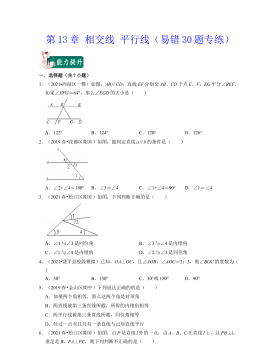
 2024-10-14 25
 -
七年级数学下册(易错30题专练)(沪教版)-第13章 相交线 平行线(解析版)VIP免费
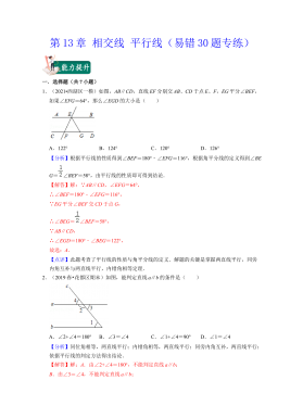 2024-10-14 28
 -
七年级数学下册(易错30题专练)(沪教版)-第12章 实数(原卷版)VIP免费
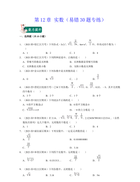 2024-10-14 27
 -
七年级数学下册(易错30题专练)(沪教版)-第12章 实数(解析版)VIP免费
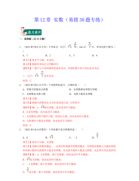 2024-10-14 19
 -
七年级数学下册(压轴30题专练)(沪教版)-第15章平面直角坐标系(原卷版)VIP免费
 2024-10-14 19
 -
七年级数学下册(压轴30题专练)(沪教版)-第15章平面直角坐标系(解析版)VIP免费
 2024-10-14 27
 -
七年级数学下册(压轴30题专练)(沪教版)-第14章三角形(原卷版)VIP免费
 2024-10-14 19
 -
七年级数学下册(压轴30题专练)(沪教版)-第14章三角形(解析版)VIP免费
 2024-10-14 30
 -
七年级数学下册(压轴30题专练)(沪教版)-第13章 相交线 平行线(原卷版)VIP免费
 2024-10-14 26
 -
七年级数学下册(压轴30题专练)(沪教版)-第13章 相交线 平行线(解析版)VIP免费
 2024-10-14 22
作者:侯斌
分类:高等教育资料
价格:15积分
属性:81 页
大小:2.65MB
格式:PDF
时间:2024-11-19

相关内容
-
七年级数学下册(压轴30题专练)(沪教版)-第15章平面直角坐标系(解析版)
分类:中小学教育资料
时间:2024-10-14
标签:无
格式:DOCX
价格:15 积分
-
七年级数学下册(压轴30题专练)(沪教版)-第14章三角形(原卷版)
分类:中小学教育资料
时间:2024-10-14
标签:无
格式:DOCX
价格:15 积分
-
七年级数学下册(压轴30题专练)(沪教版)-第14章三角形(解析版)
分类:中小学教育资料
时间:2024-10-14
标签:无
格式:DOCX
价格:15 积分
-
七年级数学下册(压轴30题专练)(沪教版)-第13章 相交线 平行线(原卷版)
分类:中小学教育资料
时间:2024-10-14
标签:无
格式:DOCX
价格:15 积分
-
七年级数学下册(压轴30题专练)(沪教版)-第13章 相交线 平行线(解析版)
分类:中小学教育资料
时间:2024-10-14
标签:无
格式:DOCX
价格:15 积分