锥盒形件分区压边拉深的成形性能研究

VIP免费
3.0 陈辉 2024-11-20 10 4 2.85MB 102 页 15积分
侵权投诉
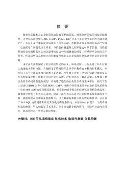
摘 要
锥盒形件是锥形和矩形形状的组合,既有锥形件易起皱的特点,又有矩形件
变形不均匀的特征。成形过程是拉深和胀形的复合成形,容易产生外皱、内皱和
破裂等缺陷,实际中常通过压边力来控制。压边力是拉深成形的一个重要工艺参
数,其主要作用是用来产生摩擦阻力,以增加板料中的拉应力,控制材料的流动,
避免起皱。然而对于不规则零件,由于拉深过程中板料凸缘不同位置对压边力的
需求是不一致的,如果在板料上都施加相同的压边力,就容易导致局部缺陷。所
以最好采用分区压边的方式,根据零件变性特点与材料流动规律,合理划分多个
区域,并施加不同的压边力。
本文采用板料成形专用软件 DYNAFORM 对板厚为 0.8mm 的 St16 材料进行了锥
盒形件有限元模拟,旨在优化工艺参数、避免各种缺陷、预报成形极限,提高锥
盒形件的成形性能。首先对锥盒形件进行了整体压边圈模拟,以确定不起皱不破
裂的安全压边力范围。接着根据零件形状、毛坯流动情况、受力分布情况等对整
体压边圈进行了分区,初次分区决定分为长边区、短边区和圆角区三个部分共八
分块,通过模拟结果讨论了各区域对成形件的影响。为使材料流动更加均匀、降
低直边区域内皱的可能、细化各分块压边力对零件的影响,最后在前述分析结果
的指导下,对分区方案进行了优化,进行十二分块压边。分析方法采用了可以考
虑交互作用的 析因设计,可以研究各分块影响的大小和方向。最终得出结论:
各压边力对成形件影响的大小为:D>C>B>CD;当分块压边圈上单位面积压边力组
合为 A=B=5MPa,C=4MPa,D=3MPa 时,能够获得最佳效果,使零件既无破裂皱曲缺
陷,又可显著提高零件的最小厚度。模拟结果表明:分区压边力拉深所得到的零
件的回弹量非常小,要小于整体式压边拉深得到的零件。最终在实验室已有的由
锻压设备和液压设备组成的单动拉深机上进行了实验,验证了分区压边的合理性
与可靠性。
关键词:板材成形 锥盒形件 分区压边力 数值模拟 析因设计
回弹
ABSTRACT
Tapered rectangular box (TRB) is a combination of conical and rectangular shapes,
not only have the characteristics of conical part of easy to wrinkle, but also have the
non-uniform deformation characteristics of rectangular part. The forming process is a
combination of drawing and bulging. And It is easy to make defects such as outter
wrinkles, inner wrinkles and rupture, so in the Actual production often controlled by the
BHF. The BHF is an important parameter in the deep drawing process, and its main role
is to generate friction to increase the tensile stress, to control the flow of material, to
avoid wrinkles. However, for irregular parts, the demand of BHF of flange at different
positions is inconsistent. If both apply the same BHF, it is easily to lead to local defects.
So we should apply the segmented blank-holder force (SBHF), according to part
variability characteristics and flow regulation, a reasonable division multiple areas, and
impose different BHF.
In this paper, The Finite element method (FEM) is carried out based on the St16
material with thickness 0.8mm to produce the TRB with the sheet metal forming
software DYNAFORM. Its purpose is to optimize the process parameters, to avoid all
kinds of defects, forming limit prediction to improve the forming performance of TRB.
First, Simulations is carried with the whole blank holder to determine the safety range
of BHF. Second, make the whole blank holder to some partition by the part shape,
material flow and force. Initial zoning decision is divided into long border, short border
and corner areas, a total of eight blocks of three parts, then discussed the regional
impact of the formed parts by the simulation results. To make more uniform material
flow, reducing the possibility of direct border area wrinkles, refine block blank holder
force on the part , and finally under the guidance of the foregoing analysis, the partition
scheme has been optimized, we introduce twelfth of the segmented block blanks. A 2K
factorial design method is carried out, which can take account of the interaction, it can
study the size and direction of each block. And finally we conclude: The influence of
the blank holder force on the formed parts is: D>C>B>CD; When the segmented BHF
per unit area of combination A = B = 5MPa, C = 4MPa, D = 3MPa, then can get the
best results. It can significantly improve the minimum thickness of the par. Also the
results show that: springback of the part obtained by segmented blank-holder is very
small, less than the drawing part by integral blank holder. Finally, experiment is carried
out on a single action drawing machine to verify the rationality and reliability of
segmented blank-holder.
Key words: Sheet Metal Forming, Tapered Rectangular Box,
Segmented Blank-holder Force, Numerical Simulation,
Factorial Design, Springback
目 录
中文摘要
ABSTRACT
第一章 绪 论 ................................................... 1
§1.1 课题的来源、目的及意义 ................................. 1
§1.2 锥盒形件拉深成形特点 ................................... 2
§1.2.1 圆锥形件的拉深 ................................... 2
§1.2.2 矩形盒件的拉深 ................................... 3
§1.3 国内外压边力控制研究现状 ............................... 4
§1.3.1 试验法 ........................................... 4
§1.3.2 理论法 ........................................... 6
§1.4 本文研究内容 ........................................... 7
第二章 板材冲压成形的有限元理论 ................................. 9
§2.1 动力显示算法 ........................................... 9
§2.2 屈服准则 .............................................. 11
§2.2.1 各向同性屈服准则 ................................ 11
§2.2.2 正交各向异性屈服准则 ............................ 12
§2.2.3 各向异性屈服准则 ................................ 13
§2.3 流动规律 .............................................. 14
§2.4 硬化规律 .............................................. 15
§2.4.1 等向硬化(Isotropic Work Harding) .............. 15
§2.4.2 随动硬化(Kinematic Harding) ................... 15
§2.4.3 混合硬化(Combined Hadring) .................... 16
§2.5 本构关系 .............................................. 16
§2.6 板壳单元模型 .......................................... 18
§2.6.1 Hughes-Liu 壳单元 ............................... 19
§2.6.2 Belytschko-Tsay 壳单元 .......................... 19
§2.7 接触问题的处理 ........................................ 19
§2.7.1 接触类型 ........................................ 20
§2.7.2 接触的分类 ...................................... 20
§2.7.3 接触算法 ........................................ 21
§2.7.4 接触搜索方式 .................................... 21
§2.8 本章小结 .............................................. 22
第三章 锥盒形件拉深缺陷分析及其预报 ............................ 23
§3.1 拉裂 .................................................. 23
§3.1.1 拉裂的分类 ...................................... 23
§3.1.2 拉裂的控制 ...................................... 24
§3.2 起皱 .................................................. 24
§3.2.1 起皱的机理 ...................................... 24
§3.2.2 起皱的分类 ...................................... 25
§3.2.3 起皱的控制 ...................................... 26
§3.3 皱曲和破裂的极限预报 .................................. 26
§3.3.1 正多边形件皱曲和破裂的极限预报 .................. 27
§3.3.2 圆锥形件皱曲和破裂的三极限预报 .................. 30
§3.4 本章小结 .............................................. 34
第四章 冲压数值模拟关键技术研究 ................................ 35
§4.1 内部因素 .............................................. 35
§4.1.1 应变硬化指数 n .................................. 35
§4.1.2 厚向异性指数 r .................................. 35
§4.1.3 屈服强度 ..................................... 36
§4.1.4 屈强比 ................................... 36
§4.1.5 延伸率 ........................................ 37
§4.2 外部因数 .............................................. 37
§4.2.1 压边力 .......................................... 37
§4.2.2 毛坯尺寸 ........................................ 38
§4.2.3 摩擦系数 ........................................ 41
§4.2.4 凸模速度 ........................................ 43
§4.3 本章小结 .............................................. 44
第五章 锥盒形件分区压边的模拟与实验 ............................ 45
§5.1 DYNAFORM 软件简介 ..................................... 45
§5.2 有限元模型的建立 ...................................... 45
§5.2.1 CAD 几何建模 .................................... 45
§5.2.2 毛坯设计 ........................................ 46
§5.2.3 毛坯材料 ........................................ 47
§5.2.4 材料模型 ........................................ 47
§5.2.5 壳单元选择 ...................................... 48
§5.2.6 沙漏 ............................................ 48
§5.2.7 网格的划分 ...................................... 49
§5.3 整体压边圈仿真 ........................................ 49
§5.4 八分块压边圈仿真 ...................................... 53
§5.4.1 长边区压边力的影响 .............................. 55
§5.4.2 短边区压边力的影响 .............................. 57
§5.4.3 圆角区压边力的影响 .............................. 58
§5.4.4 改善压边力 ...................................... 59
§5.5 十二分块压边圈仿真及优化 .............................. 61
§5.5.1 析因设计 ........................................ 62
§5.5.2 方差分析 ........................................ 64
§5.5.3 拟合曲线 ........................................ 64
§5.5.4 模型适合性检验 .................................. 65
§5.5.5 因子效应 ........................................ 66
§5.5.6 优化 ............................................ 70
§5.6 分区压边实验 .......................................... 72
§5.6.1 分区压边装置 .................................... 72
§5.6.2 实验结果分析 .................................... 73
§5.7 本章小结 .............................................. 75
第六章 回弹分析 ................................................ 77
§6.1 回弹的力学机理 ........................................ 77
§6.1.1 弯曲应力分析 .................................... 77
§6.1.2 弯曲后的回弹 .................................... 79
§6.2 回弹的影响因数 ........................................ 80
§6.2.1 成形过程的影响因素 .............................. 80
§6.2.2 回弹过程的影响因素 .............................. 82
§6.3 回弹的计算 ............................................ 82
§6.3.1 常用的回弹计算方法 .............................. 82
§6.3.2 回弹的有限元仿真 ................................ 84
§6.4 锥盒形件回弹仿真 ...................................... 84
§6.5 本章小结 .............................................. 88
第七章 结论 .................................................... 89
参考文献 ........................................................ 91
在读期间公开发表的论文和承担科研项目及取得成果 .................. 95
.......................................................... 96
摘要:

摘要锥盒形件是锥形和矩形形状的组合,既有锥形件易起皱的特点,又有矩形件变形不均匀的特征。成形过程是拉深和胀形的复合成形,容易产生外皱、内皱和破裂等缺陷,实际中常通过压边力来控制。压边力是拉深成形的一个重要工艺参数,其主要作用是用来产生摩擦阻力,以增加板料中的拉应力,控制材料的流动,避免起皱。然而对于不规则零件,由于拉深过程中板料凸缘不同位置对压边力的需求是不一致的,如果在板料上都施加相同的压边力,就容易导致局部缺陷。所以最好采用分区压边的方式,根据零件变性特点与材料流动规律,合理划分多个区域,并施加不同的压边力。本文采用板料成形专用软件DYNAFORM对板厚为0.8mm的St16材料进行了锥盒...

展开>> 收起<<
锥盒形件分区压边拉深的成形性能研究.pdf

共102页,预览10页

还剩页未读, 继续阅读

作者:陈辉 分类:高等教育资料 价格:15积分 属性:102 页 大小:2.85MB 格式:PDF 时间:2024-11-20

开通VIP享超值会员特权

  • 多端同步记录
  • 高速下载文档
  • 免费文档工具
  • 分享文档赚钱
  • 每日登录抽奖
  • 优质衍生服务
/ 102
客服
关注